Working Of Inverters And Functions Of Relays

Working Of Inverters And Functions Of Relays

Working Of Inverters And Functions Of Relays

An inverter is one of the useful devices which are used as a power backup for uninterrupted power supply. It is mainly required when there are frequent power outages in your locality. The inverter offers the supply of constant power to the AC voltage when the AC main is not available. There are several popular UPS manufacturers in Chennai. To understand the functioning of an inverter, you must understand its operation under various situations.

Detailed workings of an Inverter is explained below for a better understanding.

AC Power- Available

When there is power available, and thus reaches to the relay and battery charging section of the inverter. The supply would come from the AC mains, and the entire load would be from line voltage. This voltage is also offered to charge the inverter where it is converted into a DC voltage. When the battery or inverter is wholly charged the charging process is stopped.

AC Power-Not Available

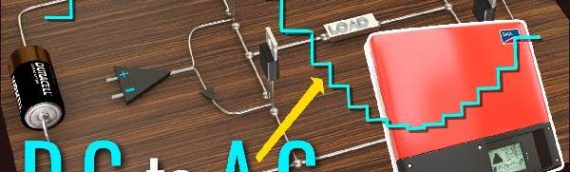
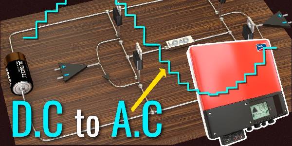
When the main current supply is not available, the oscillator circuit present inside the inverter generates and drive signal called MOS drive signal. This signal is amplified in the section where the driver is present, and it reaches the output of the inverter. The switching operation takes place with MOSFETs and transistors, and they are connected as a primary winding of the inverter transformer. When the MOS signal is generated and the switching device turns ON and OFF at the rate of 50HZ. This results in an AC current of 220V at the inverter transformer. This is available in the output socket through a change over relay.

The circuit of an inverter can able to manage various situations like overload, low battery, etc. Thus it can handle the inverter condition standby or running mode. Therefore it is possible to switch the battery to OFF or charging mode. The various working modes can be indicated with the help of the LED lights that are provided in the inverter.

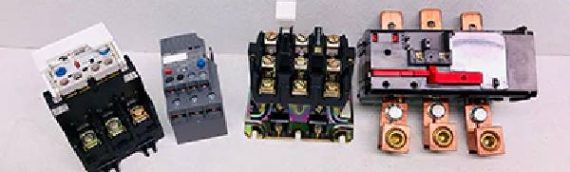
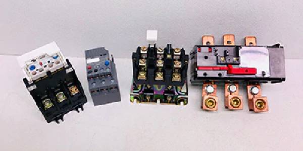
How Does Relay work?

Relays and its Working PrincipleIt is basically an electromagnetic switch which is used in the circuit of an inverter. When a single power controls a circuit, then this component is made use of to turn on and off a particular circuit. Various industrial application devices make use of relays for its effective functioning.

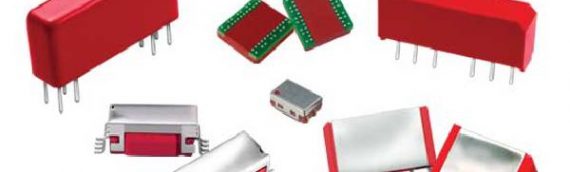
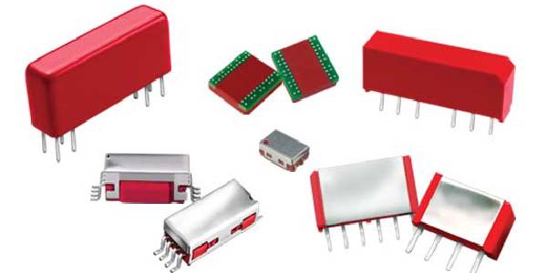
The basic principle behind the working of a relay is electromagnetic switching. Some of the essential parts of the relay are electromagnet, armature, switch point contact, spring.

The power is offered to the electromagnet with the help of a control switch. When constant current starts flowing, it energizes the electromagnet which creates an intensified magnetic field.

The two basic operations with relays are low voltage and high voltage applications.

The above is the essential operation of an inverter and the functions of a relay in an inverter. The knowledge about the workings of inverter and relays would be of great use.

Read More : Benefits Of Using Reed Switch Technology


Benefits Of Using Reed Switch Technology

Benefits Of Using Reed Switch Technology

Benefits Of Using Reed Switch Technology

Reed Switch Technology is used in low power metering applications. This is an innovative technology which offers several other benefits. Reed switch technology is a mature technology which is known for its simplicity and reliability. You know that reed switches were used for low power and battery operated applications. Low power consumption is the critical characteristic of the reed switch technology. Customizing the application to specific requirements is possible. The following are the benefits of using reed switch technology.

What are the advantages in using Reed Switches ?

Low Operating Power

This technology is based on low operating power; thus it requires little power compared to MR and Hall effect sensors. This is achieved by the use of a low duty cycle of active sensing. This makes use of constant current to run the oscillator. The reed switches do not require power for its operations and are called passive components. Lower power consumption is achieved with the use of Reed Switches. Thus it reduces cost and the battery size requirements. Therefore make use of reed switches for power-sensitive applications with greater power efficiency.

Tight Power Usage Tolerance

Solid state devices operate with the maximum operating current; thus it draws maximum current from the batteries. This would reduce the lifetime of the product. With reed switch, the current draw is set by resistor and power supply rail. The power supply is tighter than solid devices. Thus power consumption is lowest with the reed switch.

Precise Magnetic Sensitivity

Sensitivity to a magnetic field is an essential feature of Reed switch. This is measured in terms of ampere-turns and this directly proportional to the current in the coil multiplied by the number of turns. The reed switches are accurate than the solid state digital switch. This is required for the functioning under various conditions.

Simple Customization

Solid state switches come with one standard size that fits all the applications. The sensitivity ranges vary in wide ranges. If the application does not meet your requirement, then it is not possible for a custom solution.

Reed switches come with custom sensitivity ranges, and it can be customized to satisfy the specific requirements of the application. Applications may require a varied range of sensitivity. This versatility makes the reed switch technology mostly preferred by people for all applications. Reed switches come with various options like mechanical packaging, termination options, etc. so that it can be fit in various applications. Reed switches can be used continuously without any break with a speed of hundreds of time per second.

Inherent Switch point Hysteresis

Hysteresis is nothing but the difference in the magnetic field between the operating point and release point of a device. Hysteresis is required for metering applications. In solid-state devices, hysteresis should be created, but with the reed switch, it posses inherent hysteresis and offers better reliability to metering applications.

The above are some of the essential benefits of using reed switch technology in various applications. It is possible to save a lot of money with the help of reed switch technology. Thus the use of reed switch technology offers the above benefits to low metering applications.

Read More : A Clear Overview Of Reed Relay

Things To Know About Thermal Overload Relays

Things To Know About Thermal Overload Relays

Things To Know About Thermal Overload Relays

Thermal overload relays are useful electrical devices which are used to protect the functioning of motors. It mainly prevents the damage of motor due to overload. Thus thermal overload relays are constructed based on the principle that it would cut power to the motor when too much of current flows for a particular period. Thus thermal overload relays are mostly closed relay. In a motor circuit when there is an increase in temperature, due to excessive current flow, then the relay opens based on the relay type.

Thermal overload relays are similar to the circuit breakers that you install for overload. The main difference between overload relays and circuit breakers is that circuit breakers would interrupt the circuit at the very instant when the overload occurs. But a relay waits for a considerable period and then interrupts the circuit if the overload continues. Thus relays permit overload for an extended period.

Things To Know about Thermal Overload Relays

Overload Relay Types

There are three different types of overload relays. They are detailed below.

Bimetallic Thermal Relays: This type of relays make use of a bimetallic strip which opens mechanically. This includes two types of metallic strips with different expand rates when exposed to heat. Thus the metallic strip bends when the temperature increases. A spring is attached to the metallic strip. The spring gets pulled when the excess heat makes the metallic strip to bend. Thus the contacts are pulled, and the circuit is broken. When the bimetallic strip gets cooled, then it gets its original shape.

Solid State Relays: This is an electronic device which does not contain any moving mechanical parts. The relay operates by calculating the average temperature of the motor. This is done by tracking the starting and running currents. It is better to make use of solid state relays as it is faster other than other types of relays. It also features adjustable set points and trip times. Thus they are used in explosive environments.

Temperature Control Relays: The temperature of the motor is sensed by a thermistor or resistance thermal device. These are embedded in the motor winding — the resistance of the device increases as the temperature increases. The threshold circuit detects the increase, and this opens the relay contacts.

Electrical Rating

The following are some of the electrical relay specifications.

Tripping: This is the general term used when the circuit interrupts due to overload.
Full load current range: This is the current range to be set with the relay
Temperature trip Range: This term applies to the relays which measure current instead of temperature.
Trips Class: This is the minimum time that a relay can withstand overload.

Features

Some of the essential features of thermal overload relays are listed below.

  • The automatic reset is the feature of the overload relay that returns to the original position after some specified time.
  • Ambient temperature compensation is a feature that works efficiently for ambient temperatures.
  • Phase monitoring is done to avoid motor damage.
    The above are some of the things to know about thermal overload relays.

Read More : A Detailed Overview Of Thermal Relay

A Clear Overview Of Reed Relay

A Clear Overview Of Reed Relay

A Clear Overview Of Reed Relay

Reed relay is an electronic device which contains a reed switch, a coil that creates a magnetic field, a diode for managing the back EMF generated from the coil. It is a package encapsulated with different connection terminals. Reed relay is a device which makes use of low resistance metallic switch path.

Basic Overview of Reed Relay and its Working

Reed Switch

This switch is made up of two metallic blades. This is made up of ferromagnetic material which is sealed with glass material. This seal is called a hermetic seal which helps to prevent the contaminants from entering the critical area called the contact area. Mostly the reed switch is in open contact in normal state.

The presence of a magnetic field that is applied along the axis of the reed blades intensifies the magnetic field. The reed blades are, and this increases the magnetic field further. The open contact makes the reed blades to attract each other, and this deflects the blades. With the creation of the magnetic field, the blades touch each other and this result in electrical contact.

The reed switch does not contain any movable parts except the blade. This is because the switch does not include any pivot points which helps in movement. The switch area or the contact area is sealed hermetically by using a glass envelope and filling it with inert gas. You can also make use of a vacuum to fill the glass envelope. Sealing the contact area offers a long mechanical life.

The reed switch design is of variable size. The deflection of blades does not take place in case of longer switches. Deflections take place quickly in case of short reeds this because the short reeds are made up of thinner material. This creates a great impact on the contact area and its rating. With small reed switches, small relays can be constructed. It is better to make use of larger switches as it is mechanically robust with great contact area. This improves the signal carrying capability.

The contact area of the switch is made of several plating materials like rhodium, ruthenium, iridium which belong to the rare platinum group. These are wear resistant, hard and possess greater resistance stability. This is the reason for its long life and extended operation time. Tungsten is the preferred material in high voltage conditions due to its high melting point and resistance. The contacts of the reed switch can also be coated with other materials like electroplating and vacuum deposition.

Generating Magnetic Field

A reed relay operates with the help of the magnetic field created which closes the reed switch contacts. In reed relays the magnetic field is built with the help of the coil. The current is passed in between the coil. The axial magnetic field is generated by the coil which closes the reed contacts.

Different levels of the magnetic field should be generated to close the contacts of various types of reed switches.
The above is the basic overview of reed relay and its working.

Read More : Things To Know About Thermal Overload Relays

A Detailed Overview Of Thermal Relay

A Detailed Overview Of Thermal Relay

A Detailed Overview Of Thermal Relay

Thermal relay is an electrical component which is used in various electrical appliances. It is used for specific applications. The thermal relay works on a particular principle which one should be aware before knowing about its construction. It is used primarily in electrical fixtures to protect from overcurrent. Mostly thermal relays are installed in motors to avoid damage of motor due to power overload. Here you would know about the principle, construction, and applications of Thermal Relay.

Construction and Working of Thermal Relay  

Basic Principle

The principle on which the thermal relay works is the thermal effect with electrical energy. Different element possesses a different coefficient of thermal expansion. Thus when two metals are heated together, then one with a higher coefficient of thermal expansion will expand more than that of the other metal. This is the basic principle used with a thermal relay.

Construction And Working

The essential parts of the thermal relay required for its construction are bimetallic strips, heating coils, and current transformers. The current transformer serves as a source of electrical supply to the heating coils which generate thermal energy. This would, in turn, heat bimetallic strips. Nickel and steel alloys are used to create the bimetallic strips. These alloys are steel resistive, and it prevents from thermal aging.

The construction of the thermal relay simple; thus it is used in motors and other devices for preventing it from overload. You need a bimetallic strip of two different metals each with different coefficient of expansion. Consider metal A with a lower coefficient of thermal expansion and metal B with a high coefficient of expansion. Thus metal B would expand more when it gets heated, and the metallic strip would bend towards the metal A. Thus the No contact is closed, and ultimately the circuit breaker works as the trip coil gets energized.The heating effect created is not instantaneous, and it is based on Joule’s law of heating.

H the amount of heat is proportional to the square of current and resistance concerning time. Thus there would be a prolonged time delay for the operation of thermal lag. This type of relay is used in devices where the overload is allowed for a particular period. If the current falls in between the normal value, the relay would be not be operated. The main application of thermal relay is the protection of an electric motor from overload.

The overload relay is installed in the motor in places where temperature varies. The overload trip point would change based on the temperature of the surrounding. This would result in premature tripping. Special overload relays called as ambient compensated bimetal overload relays are used to combat this issue.

The overload relay is generally used on an inverse time curve where the tripping time becomes less when the current flow increases. They are measured based on trip class. It is nothing but the length of time it takes for the relay to open when an overload occurs. Some of the common trip classes are class 5,10,20,30. Class 5 is used for motors.
The above offers a detailed overview of thermal relays.

Read More : Guide to Understanding Switching Systems